Example wiring scheme for connecting an IPG Laser YLS-AMB laser to the SP-ICE 3 Card.
Wiring
Caution
RAYLASE GmbH makes no warranty concerning the completeness, reliability, or accuracy of this information.
Any action you take on the basis of the information in this document is strictly at your own risk, and
RAYLASE GmbH will not assume responsibility for any damage to property or injury to persons.
RAYLASE GmbH is not responsible for laser safety: appropriate measures must be taken by the user.
Please see also section 1.4.1 Laser Safety
Note
Although you may be able to use one or more of these schemes as a reference for your particular laser and application, please be aware that RAYLASE GmbH can neither guarantee success, nor provide individual wiring diagrams for every possible use-case or application.
In particular, RAYLASE GmbH does not guarantee the accuracy or present validity of any OEM data shown in the following sections.
Recommended Signal Mapping and Usage
For the IPG Laser YLS-AMB laser, no special I/O Signal mapping is required.
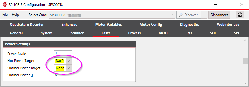
SPICE3Config: Power Settings configuration for IPG Laser YLS-AMB
The power level of the ANALOG1 and ANALOG2 signals is never automatically reset to zero.
Each signal independently retains the power level that was last assigned to it.
Changing the power level of one of them leaves the other signal unaltered.
All power level changes for these signals must be individually and explicitly commanded, either via AppendPower or via AppendDacValue.
The recommended signal configuration and usage, shown above, are not the only ones possible.
For your application you might prefer, for instance, to set the power-level for the Ring laser unit with the AppendPower(power-level) command.
For this, and assuming that the rest of the configuration remains unchanged, you would need to
set the Core laser unit's power level by calling AppendDacValue(Dac0, power-level).
Alternatively, you could simply re-wire the hardware signals on the physical connectors, thus swapping the Core/Ring assignment without requiring any changes to your application code.