6.2.2.9 Wiring Example - TRUMPF TruFiber P compact (formerly "SPI-Lasers redPOWER QUBE")
Example wiring scheme for connecting a TRUMPF TruFiber P compact (formerly "SPI-Lasers redPOWER Qube") laser to the SP-ICE-3 card.
Wiring
Caution
RAYLASE GmbH makes no warranty concerning the completeness, reliability, or accuracy of this information.
Any action you take on the basis of the information in this document is strictly at your own risk, and
RAYLASE GmbH will not assume responsibility for any damage to property or injury to persons.
RAYLASE GmbH is not responsible for laser safety: appropriate measures must be taken by the user.
Please see also section 1.4.1 Laser Safety
Note
Although you may be able to use one or more of these schemes as a reference for your particular laser and application, please be aware that RAYLASE GmbH can neither guarantee success, nor provide individual wiring diagrams for every possible use-case or application.
In particular, RAYLASE GmbH does not guarantee the accuracy or present validity of any OEM data shown in the following sections.
Recommended Signal Mapping and Usage
Caution
Note that the SP-ICE-3 Card's logic signal level is 5V, but the laser requires 24V.
Consequently, logic level converters or opto-couplers MUST be used.
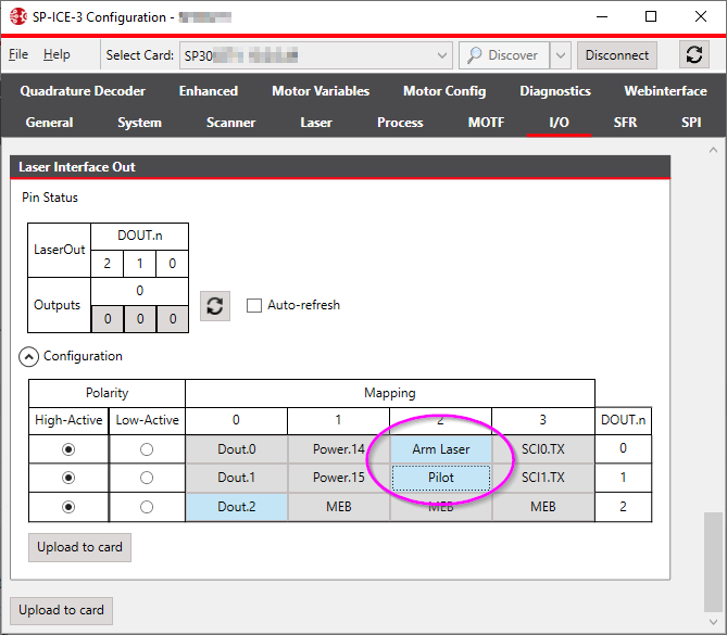
SPICE3Config: Laser Out configuration for TRUMPF TruFiber P compact (formerly "SPI-Lasers redPOWER QUBE")
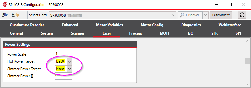
SPICE3Config: Power Settings configuration for TRUMPF TruFiber P compact laser