11.1.1.1 Configuration Procedure |
MOTF Signals and Operating Parameters can be configured according to the requirements of your particular application.
Please follow 17.1 Accessing the card with the SP-ICE 3 Configuration Tool for preparatory steps leading up to start of the following procedure.
See also: Recommended Initial Settings, below.
MOTF Configuration Procedure
Select the MOTF tab.
Scroll and resize it, if necessary, so that the required items are visible.
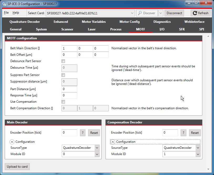
For details of signals themselves, see X902 Motf1 and X900 Motf2.
Set signals and parameters as appropriate.
The following can be used as the basis for further application-specific fine tuning of the individual values.
Recommended Initial SettingsParameter
Initial Value
Notes
Operating Mode
Leave on Standard unless you want to use Endless MOTF.
Setting this parameter to Continuous will activate Endless MOTF.
Belt Main Direction
The normalized direction vector of the main decoder relative to the field.
For example, if the process’s X axis points east and the part is northbound then the Main Direction should be set to [0,1,0].
If the part is southbound, then set the Main Direction to [0,-1,0].
Belt Offset
0, unless your application requires a fixed offset between the process’s and part’s coordinate systems
Distance per count
The expected distance represented by one encoder tick. Derive this value from the encoder’s data manual.
For example, if you employ an encoder wheel with a circumference of 50mm and 10000 ticks per revolution, then the distance per tick equals to 5 um/tick (= 50mm * 1000 um/mm / 10000 ticks).
Debounce Part Sensor
Set to enabled if the part sensor is a mechanical switch that closes/opens in the presence/absence of the part, respectively.
Required only when a part sensor is used.
If the part sensor is an optical device then enabling debouncing is optional. If there is ringing on the sensor signal line, then enabling the debounce logic will suppress any false triggers.
Debounce Time
As appropriate for your switch.
Required only when a part sensor is used.
Mechanical switch contacts notoriously bounce after every open-close and close-open transition – typically for several milliseconds, potentially causing multiple trigger signals.
Suppress Part Sensor
If the part sensor does not reliably detect just the part’s edge(s), but also produces false triggers while the part is passing by (e.g. an optical part sensor might trigger erroneously on the part’s pattern), then it is recommended to enable the suppression logic.
Required only when a part sensor is used.
Suppression Distance
The part’s length.
Required only when a part sensor is used.
Part Distance
The expected distance between the sensor’s detection of the part and the beginning of the first mark vector.
Required only when a part sensor is used.
Use Compensation
Optional, depending on application requirements.
Required only when a compensation decoder is used.
Belt Compensation Direction
The normalized direction vector of the compensation decoder relative to the field.
For example, if the process’s X axis points east and the compensation decoder detects movement northwards, the Compensation Direction should be set to [0,1,0].
To save the altered configuration to the card's non-volatile memory, click the Upload to card button.