7.1.8 Scanner Configuration Procedure |
Scanner Operating Parameters can be configured according to the requirements of your particular application.
Please follow 17.1 Accessing the card with the SP-ICE 3 Configuration Tool for preparatory steps leading up to start of the following procedure.
See also: Recommended Initial Settings, below.
Scanner Configuration Procedure for all scanners
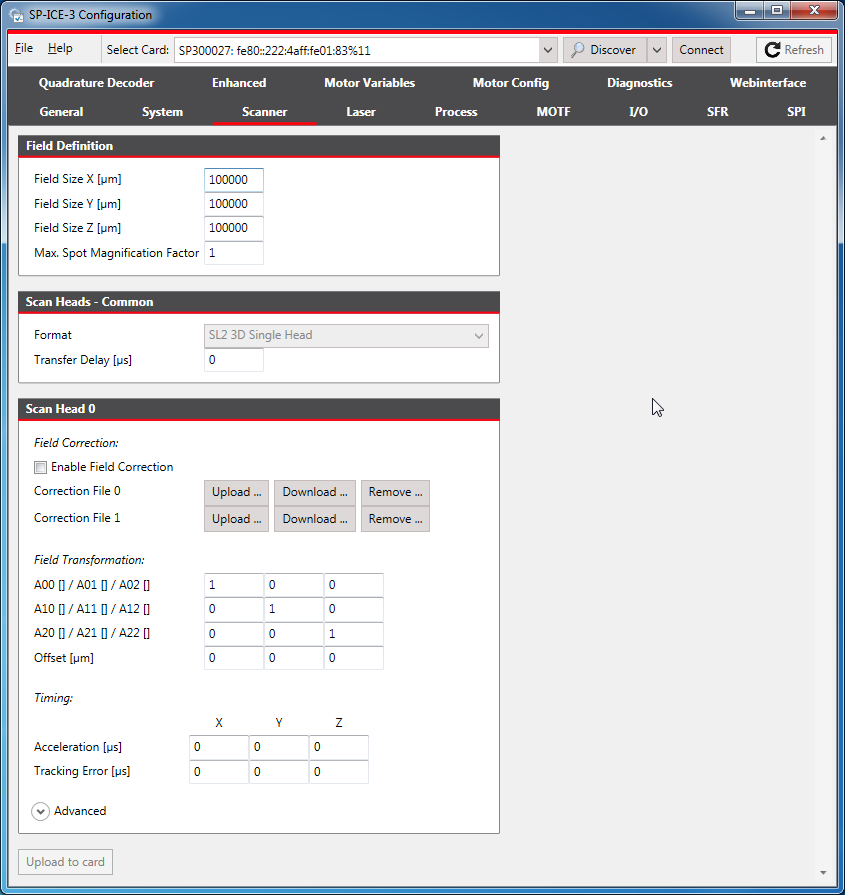
Select the Scanner tab.
Scroll and resize it, if necessary, so that the required items are visible.
For details of signals themselves, see X904 Scanner1 and X905 Scanner2.
Set signals and parameters as appropriate.
The following can be used as the basis for further application-specific fine tuning of the individual values.
Recommended Initial SettingsParameter
Initial Value
Notes
Transfer Delay
The time that elapses between the card sending a position command to the scanner, and that command being recognised by the controller algorithm in the scanner.
For more details, please refer to
Some RAYLASE digital scan heads can provide the value upon enquiry via the Enhanced Protocol.
For others, please consult the scanner's data sheets.See also: Additional Data for Digital Scanners., below.
Set to 0 if neither the scan head nor its data sheet provides an appropriate value.
Field Transformation
The identity matrix rotated by the angle between the process’s and the scanner’s coordinate systems.
For example, if the scanner’s X axis points North and the process’s X axis should point East, then use the coefficients of a rotation matrix for 90 degrees:
A00 = 0
A10 = -1
A20 = 0
A01 = 1
A11 = 0
A21 = 0
A02 = 0
A12 = 0
A22 = 1
Set the Offset to 0, unless the origins of both coordinate systems do not coincide in your setup.
Acceleration
Set to the value given in the scanner’s data manual.
Tracking Error
Set to the value given in the scanner’s data manual.
(By RAYLASE’s convention the scanner Tracking Error is 60% of the acceleration time).Set Tracking Error Z to 0 when using a 2D scan head.
To save the altered configuration to the card's non-volatile memory, click the Upload to card button.
How to display additional data
On the Scanner tab, make sure that Format (in the Scan Head - Common category) is set appropriately.
If not, you should select one now, and then click the Upload to card button.
 Note
NoteThe selected Format it must match the connection configuration of your scan system in order for the scanner data to be read back correctly by the SP-ICE 3 Card.
See: 7.1.1 Scan Head Format Definitions for details of the available Formats.
Open the Enhanced tab.
It may be necessary to click the Refresh button on the menu bar to obtain the initial display of scanner data values.
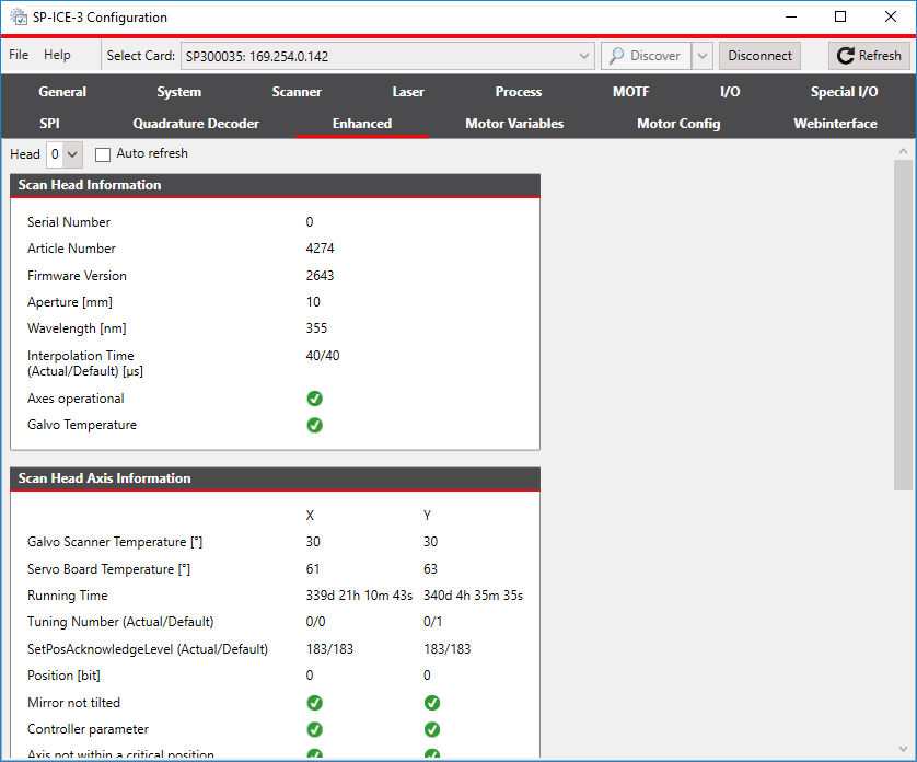
To make it easier to observe changing scanner data values, you can select the Auto refresh check-box.