3.11 Coordinate Systems and Transformations |
When handling with 2D or 3D graphics there are different coordinate systems involved. There is often the need to transform the points of an object from one coordinate system to another. This can be achieved by so-called transformation matrices which are used at several places in the API.
The points a grahical object is built of are defined in the object's own
coordinate system. In RAYGUIDE, the origin of this coordinate system is
the middle of an object.
E. g. if a MarkableRectangle with the width of
20 mm and the height of 10 mm is created, this results in the end
in a polygon with the four points (RAYGUIDE uses micrometers as unit)
( 10000, -5000, 0),
( 10000, 5000, 0),
(-10000, 5000, 0),
(-10000, -5000, 0).
This can be proved with a little application similar to the
2.4 Hello World Example:
Since nothing at all is to be marked here, section 4 can be omitted completely, and section
3 is replaced by this code (the whole solution "CoordinateSystems" is available in the sample folder
C:\Program Files\RAYLASE\RAYGUIDE\SDK\SampleCode\Tutorials\):
// 3. Create a new job:
IJobManager jobManager = markerAPI.JobManager;
JobDefinition jobDef = jobManager.CreateNewJob( "CoordinateSystems" );
jobDef.ScanControllers.Add( scanController );
// reduce the workspace's size a little to show finer rulers in the GUI:
jobDef.Workspace = new dvec3( 80000, 80000, 10 );

// 3.a) Create a rectangle of size 20mm x 10mm and print its points:
MarkableRectangle r1 = new MarkableRectangle { Size = new dvec2( 20000, 10000 ) };
PrintPoints( r1 );
To print the points there is a new method:
private static void PrintPoints( BaseMarkableVectorGraphic vg )
{
    VectorGraphicEngine vge = vg.VectorGraphicEngine;
    VectorGraphicLayer layer = vge.Layers[0];
    VectorGraphicPath path = layer.Paths[0];
    PolyLineMetafileCommand polylineCmd = (PolyLineMetafileCommand)path.Commands[0];

    Console.WriteLine( "points:" );
    foreach ( dvec3 point in polylineCmd.Points )
        Console.WriteLine( point );
}
Running this program will print the points listed above to the console.
To move the rectangle around on the canvas, the Translate(dvec3) method can be used; add a new section 3.b) to the code:
// 3.b) Add a new translated rectangle to the job and print its points:
MarkableRectangle r2 = new MarkableRectangle { Size = new dvec2( 20000, 10000 ) };
r2.Translate( new dvec3( 20000, 10000, 0 ) );     // translate the rectangle
jobDef.AddJobElement( r2 );                       // add the translated rectangle to the job
jobManager.ExportJob( jobDef, "test1.rg", "rg" ); // write the job to disk
PrintPoints( r2 );                                // print the rectangles points
The Translate() method moves the rectangle by 20 mm to the right and 10 mm up here; this can be checked when loading the file test1.rg into RAYGUIDE (screenshot in the next section).
But, as shown in the output of the points, they are unchanged and still define the rectangle in its own coordinate system. Obviously the translation information is stored elsewhere, see below.
Hint: An object of type BaseMarkablePersistentVectorGraphic can have freely arranged paths, the origin is therefore regulary not its mid point.
As could be seen in the previous section a job element's defining points are given relative to its own coordinate system. But, objects are to be put into the "real world". The real world is represented in RAYGUIDE by the coordinate system defined in the canvas. When loading the file test1.rg created in the previous section, this is the result:
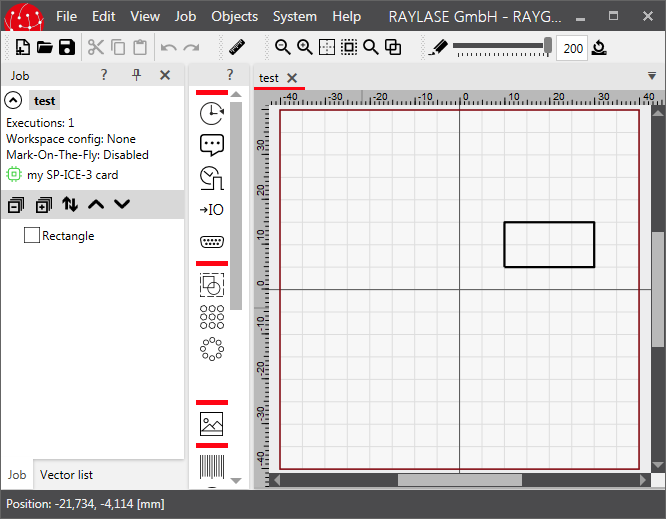
In this example our world ranges in x and y direction from -40 mm to +40 mm (the z direction, by the way, points from the screen to the user). When a job element is newly created in RAYGUIDE, it is placed always in the origin of the world, i. e. at position (0, 0, 0), and the rectangle would be centered on the canvas. Since we have translated it by 20 mm in x and 10 mm in y direction its midpoint is now at position (20 mm, 10 mm, 0 mm).
As said, a job element is always unchanged in its object coordinate system. But, when putting it into the world, it is possible to place it anywhere, to scale it, to rotate it, to mirror it or to shear it. This can be done by means of so-called transformation matrices which move each point of an object to another place when applying the matrix to the point.
We cannot go into the details here too much. We just want to mention that a transformation is represented by a 4x4 matrix which has to be applied to the position vector of a point. The common transformation matrices are:
Translation by vector [tx, ty, tz]:
[ 1 0 0 tx ]
[ 0 1 0 ty ]
[ 0 0 1 tz ]
[ 0 0 0  1 ]

Scaling by vector [sx, sy, sz]:
[ sx  0  0 0 ]
[  0 sy  0 0 ]
[  0  0 sz 0 ]
[  0  0  0 1 ]

Rotation by angle ß:
around the z-axis:         around the y-axis:          around the x-axis:
[ cos(ß) -sin(ß)  0  0 ]   [  cos(ß)  0  sin(ß)  0 ]   [ 1    0       0     0 ]
[ sin(ß)  cos(ß)  0  0 ]   [    0     1    0     0 ]   [ 0  cos(ß)  sin(ß)  0 ]
[    0      0     1  0 ]   [ -sin(ß)  0  cos(ß)  0 ]   [ 0 -sin(ß)  cos(ß)  0 ]
[    0      0     0  1 ]   [    0     0    0     1 ]   [ 0    0       0     1 ]

Mirroring:
on the xz-plane:           on the yz-plane:            on the xy-plane:
[ 1  0 0 0 ]               [ -1 0 0 0 ]                [ 1 0  0 0 ]
[ 0 -1 0 0 ]               [  0 1 0 0 ]                [ 0 1  0 0 ]
[ 0  0 1 0 ]               [  0 0 1 0 ]                [ 0 0 -1 0 ]
[ 0  0 0 1 ]               [  0 0 0 1 ]                [ 0 0  0 1 ]

Shearing:
parallel to the xy-plane:  parallel to the yz-plane:   parallel to the xz-plane:
[ 1 0 ax 0 ]               [  1 0 0 0 ]                [ 1 ax 0 0 ]
[ 0 1 ay 0 ]               [ ay 1 0 0 ]                [ 0  1 0 0 ]
[ 0 0  1 0 ]               [ az 0 1 0 ]                [ 0 az 1 0 ]
[ 0 0  0 1 ]               [  0 0 0 1 ]                [ 0  0 0 1 ]
The points are represented in so-called homogenous coordinates by 4-dimensional vectors where the 4th coordinate is set to 1. E. g. to translate the right upper corner (10 mm, 5 mm, 0 mm) of our rectangle by 20 mm to the right and 10 mm up, i. e. the translation vector is (20 mm, 10 mm, 0 mm), this matrix operation is done:
[ 1 0 0 20 ] [ 10 ]   [ 30 ]
[ 0 1 0 10 ] [  5 ] = [ 15 ]
[ 0 0 1  0 ] [  0 ]   [  0 ]
[ 0 0 0  1 ] [  1 ]   [  1 ]
In RAYGUIDE each markable job element has such a matrix which will be applied to all points building the object; it can be found in the property ModelMatrix of class MarkableConfiguration; each object of type BaseMarkableJobElement, as our rectangle is one of, has a MarkableConfiguration property.
Some of these operations, like Translate(dvec3), as seen above, or Rotate(Double), can be done with methods in class BaseMarkableJobElement. These methods set the matrix as needed for these operations. For others the matrix can be manipulated directly with methods of the GlmSharp library and hand the matrix over with method Transform(dmat4).
How does our translation matrix used above looks like? Let us add a new method for printing our ModelMatrix of type dmat4 as defined in the GlmSharp library:
private static void PrintMatrix( BaseMarkableVectorGraphic vg )
{
    Console.WriteLine( "matrix:" );
    dmat4 m = vg.MarkableConfiguration.ModelMatrix;
    PrintMatrixRow( m.Row0 );
    PrintMatrixRow( m.Row1 );
    PrintMatrixRow( m.Row2 );
    PrintMatrixRow( m.Row3 );
}

private static void PrintMatrixRow( dvec4 row )
{
    for ( int r = 0; r < 4; r++ )
        Console.Write( row[r] + "; " );
    Console.WriteLine();
}
And call this method additionally at the end of section 3.b):
PrintMatrix( r2 );
The output will not surprisingly be
1; 0; 0; 20000
0; 1; 0; 10000
0; 0; 1;     0
0; 0; 0;     1
because the translation component of a transformation matrix is stored in the last column.
The next examples show how to use the matrix directly and how to use the GlmSharp library; we add a section 3.c) and add the first, untransformed and some transformed, colored rectangles to our job:
// 3.c) Add some transformed rectangles to the job:
r1.PenNumber = 1; // set our old untransformed rectangle to black
r2.PenNumber = 2; // set our old translated rectangle to red
dmat4 transMat = r2.MarkableConfiguration.ModelMatrix; // get the translation matrix

// Create a rotated rectangle directly with a GlmSharp rotation matrix:
MarkableRectangle r3 = new MarkableRectangle { Size = new dvec2( 20000, 10000 ) };
dmat4 rotMat = dmat4.RotateZ( Math.PI / 10 );
r3.MarkableConfiguration.ModelMatrix = rotMat;
r3.PenNumber = 3; // yellow

// Create a rectangle which is first rotated, then translated:
MarkableRectangle r4 = new MarkableRectangle { Size = new dvec2( 20000, 10000 ) };
r4.PenNumber = 4; // light green
dmat4 rotTransMat = transMat * rotMat;
r4.MarkableConfiguration.ModelMatrix = rotTransMat;

// Create a rectangle which is first translated, then rotated:
MarkableRectangle r5 = new MarkableRectangle { Size = new dvec2( 20000, 10000 ) };
dmat4 transRotMat = rotMat * transMat;
r5.MarkableConfiguration.ModelMatrix = transRotMat;
r5.PenNumber = 5; // green

// Add the job elements and save the job:
jobDef.AddJobElement( r1 );
jobDef.AddJobElement( r3 );
jobDef.AddJobElement( r4 );
jobDef.AddJobElement( r5 );
jobManager.ExportJob( jobDef, "test2.rg", "rg" );
As shown with rectangles r4 and r5 transformation matrices can be combined easily by just multiplying them. But attention: The order matters! r4 is first rotated and then translated, r5 the other way round. When multiplying the matrices the sequence is from right to left.
When loading the resulting file test.rg the job looks like this:
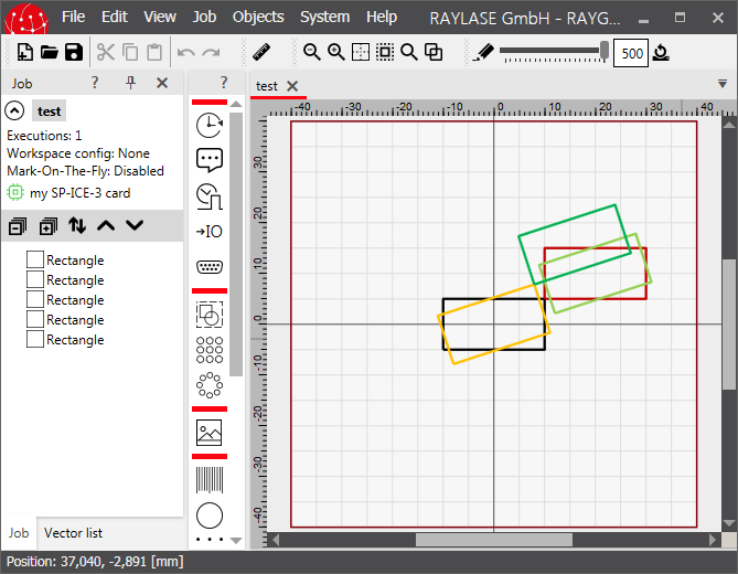
The black rectangle is the original, untransformed one.
The red is the same as we have seen before with a translation of 20 mm to the right and 10 mm up.
The yellow one is rotated around the z-axis by an angle of PI/10.
The light green rectangle is first rotated by the same angle and then translated.
The dark green rectangle is first translated and then rotated.
If it comes to transforming a dvec3 point p1 by means of a transformation matrix dmat4 m into a dvec3 point p2, this can be done in this way with the GlmSharp library:
Create a 4-dimensional vector out of the 3-dimensional vector by setting the 4th coordinate to 1:
p1Temp = new dvec4(p1.x, p1.y, p1.z, 1);Multiply the matrix m at the right side with the 4-dimensional point:
p2Temp = m * p1TempCreate the result by getting the first three coordinates of the transformed vector:
dvec3 p2 = new dvec3( p2Temp.x, p2Temp.y, p2Temp.z );
Using some convenience methods of the GlmSharp library these three
steps can be performed in a single line as well:
p2 = new dvec3( ( m * new dvec4( p1, 1 ) ).xyz );
To tell the truth it is very often not so clear what the "world" is. Say, there is a nested structure of objects where the objects are part of a group. Of course one wants to place all objects relative to each other in the group, and the group then as a whole in the world. In this case the ModelMatrix of an object describes its relative position and rotation in the group, and the ModelMatrix of the group the group's position and rotation in the world. Or, if the group is in another group, the position and rotation in this group ...
An example is shown here when adding these lines as section 3.d):
// 3.d) Put an untransformed and an transformed rectangle into a transformed group:
MarkableGroup grp = new MarkableGroup();          // create a group
grp.AddJobElement( r1 );                          // add our untransformed rectangle r1 to it
grp.AddJobElement( r2 );                          // add our translated rectangle r2 to it
grp.Translate( new dvec3( -20000, 10000, 0 ) );   // transform the whole group
jobDef.ClearAllJobElements();                     // remove all old job elements
jobDef.AddJobElement( grp );                      // add the group
jobManager.ExportJob( jobDef, "test3.rg", "rg" ); // save the job to disk
A new group is created here and the previously defined rectangles r1 (the black untransformed one) and r2 (the red translated one) are put into it. Then the whole group is translated by vector (-20 mm, 10 mm, 0) 20 mm to the left and 10 mm up. To make the effect better visible the job is cleared from our old rectangles and only the new group is added. The result is this:
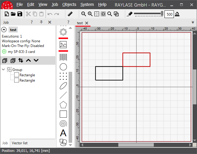
As expected both translations are applied to the red rectangle: The first one relative to the group and then the second one relative to the world.
In section 3.3 Important Classes is explained that the job element holder holds the transformation matrix for transforming an object into its parent coordinate system. But, the holder class is not mentioned here yet. The cause for this is: The holder is not needed to handle the transformations when creating jobs with the API. The developer can stick to the pure job elements if he likes it. The RAYGUIDE GUI uses the holder class instead, to make things easier for its internal handling of the objects.
There is only one disadvantage when not using the holders: If a job, created in this way, is loaded into the RAYGUIDE GUI, the transformations are not displayed in the object transformation panel; and if an transformation is added there, it will be applied additionally to the one defined in the job element.
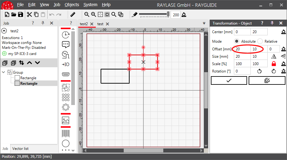
This means: If a job which has been originally created with the API is to be worked on further in the GUI, the transformations should be stored in the job element holders, not in the job elements. The next example does the same as the last one. I. e. we create a new rectangle r6, create a new group grp2, put the old, untransformed rectangle r1 and the new one r6 into it and add the group to the job (after removing all old objects from it). The holders are created when adding a job element to the job automatically. Now we get the job element holders back from the just created job and apply our transformations to the holders instead to the job elements:
// 3.e) Using the job element holders instead of the job elements for storing the transformations:
MarkableRectangle r6 = new MarkableRectangle();        // create a new rectangle
MarkableGroup grp2 = new MarkableGroup();              // create a new group
r6.Size = new dvec2( 20000, 10000 );                   // set the size of the new rectangle
r6.PenNumber = 2;                                      // set the rectangles pen to red
grp2.AddJobElement( r1 );                              // add the old rectangle to the group
grp2.AddJobElement( r6 );                              // add the new rectangle to the group
jobDef.ClearAllJobElements();                          // remove all old job elements
jobDef.AddJobElement( grp2 );                          // add the group to the job to create all holders
JobElementHolder grp2Holder = jobDef.JobElements[0];   // get the group's holder which is the first job element
JobElementHolder r6Holder = grp2Holder.Children[1];    // get the holder of rectangle r6 which is the second child of the group
r6Holder.Translate( new dvec3( 20000, 10000, 0 ) );    // apply the translation to the holder of r6
grp2Holder.Translate( new dvec3( -20000, 10000, 0 ) ); // apply another translation to the holder of the group
jobManager.ExportJob( jobDef, "test4.rg", "rg" );      // save the job to disk
When loading the jobs "test3.rg" and "test4.rg" into RAYGUIDE the difference can be seen: Only in job "test4.rg" the offsets are displayed in the transformation panel:
Some transformations are applied automatically in the background by RAYGUIDE when executing a job. These will be listed here.
Field Correction
A scan head produces some natural deviations from the wanted locations when positioning the laser beam, which needs to be compensated. This is done by defining a set of correction data bundled in a correction file. A correction file can be assigned to a scan head with the property BaseScanHeadCorrectionFile. It will be taken into account by the SP-ICE 3 card when BaseScanHeadEnableFieldCorrection is set to true.
Some basic data in the file can be retrieved with method CorrectionFileAnalyzerGetCorrectionFileInfo(String).
Field Calibration
Mainly to compensate little mechanical inaccuracies in the machine arrangement where the scan head is built in, there is the field calibration. It allows to translate, scale and rotate each object to some extent while marking it. This transformation can be set with property BaseScanHeadCalibration.
Workspace Offset
When using workspaces in a job (see section "Workspace" in the RAYGUIDE User Manual), a field offset can be assigned to a controller card. A workspace is configured with class RAYLASE.Marker.ConfigurationWorkspaceConfiguration. It contains with property WorkspaceConfigurationScanControllers a list of scan controller settings, one setting for each scan controller used in the workspace. Class RAYLASE.Marker.ConfigurationWorkspaceConfigurationScanControllerSettings again has the property WorkspaceConfigurationScanControllerSettingsOffset to set the offset.
Process Transformation
In the GUI the process transformation can be modified even while a job is running by means of the Process adjustment panel to apply an additional scaling, rotation or offset to the job elements. In the API the same can be achieved with the method BaseScanControllerSetProcessTransformation(dmat4). To read the current values there is the corresponding method BaseScanControllerGetProcessTransformation.
MOTF
Mark on the fly means to put the objects to be marked on a conveyor belt and move them continuously through the workspace. The conveyor belt will often move parallel to the workspace's x-axis and parallel to its x-y-plane. If this is not the case, an azimuth and an elevation angle can be defined. Both are properties in class RAYLASE.Marker.Device.ScanControllerMotfDirection, which is a property in class RAYLASE.Marker.Device.ScanControllerMotfDecoderProfile, which is a property in class RAYLASE.Marker.Device.ScanControllerMarkOnTheFlyProfile, which is a property in class RAYLASE.Marker.Device.ScanControllerBaseScanController. The angles are defined as shown in this picture:
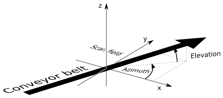
The azimuth angle will rotate an object on the belt in a way that the orientation is the same as in the canvas, regularly its edges will be parallel to the movement direction.
The execution angle
allows us to place the objects onto
the belt not parallel to the movement direction but with this angle added.
Some production environment will need this.
The angle can be set with property
WorkspaceConfigurationMarkOntheFlySettingsAngle
in class
RAYLASE.Marker.ConfigurationWorkspaceConfigurationMarkOntheFlySettings.
An object of this class is the property
WorkspaceConfigurationMotfSettings
in class
RAYLASE.Marker.ConfigurationWorkspaceConfiguration
which is mentioned in the previous section.